
Structural Analysis · DTEX CAE
Behind every collapse, a calculation
DTEX CAE is a structural analysis and collapse analysis software developed by DTEX, with all rights owned by DTEX. In silo, chimney and building demolition it calculates, before the blast, which members are to be cut, where the load will be transferred, and in which direction and sequence the structure will collapse.
01What it does
From drawing to collapse analysis in one tool
DTEX CAE brings every step of demolition engineering into a single model. Each step is linked to the record of the previous one; every result can be traced back to its source. The program does not decide; it lays out the calculation so that the engineer can.
- 01
Model
3D model from drawings: columns, beams, shear walls, slabs and reinforcement.
- 02
Structural analysis
3D frame, buckling and modal analysis; demand/capacity ratio for every member.
- 03
Critical members
Where the load goes when a load-bearing member is removed, and which members are overstressed.
- 04
Demolition scenario
Members to be cut, stages and delay sequence, felling direction.
- 05
Collapse analysis
Separation and collision of members and formation of the debris with AEM, time step by time step.
- 06
Report
Method statement, technical and client report, reinforcement quantities, summary presentation.

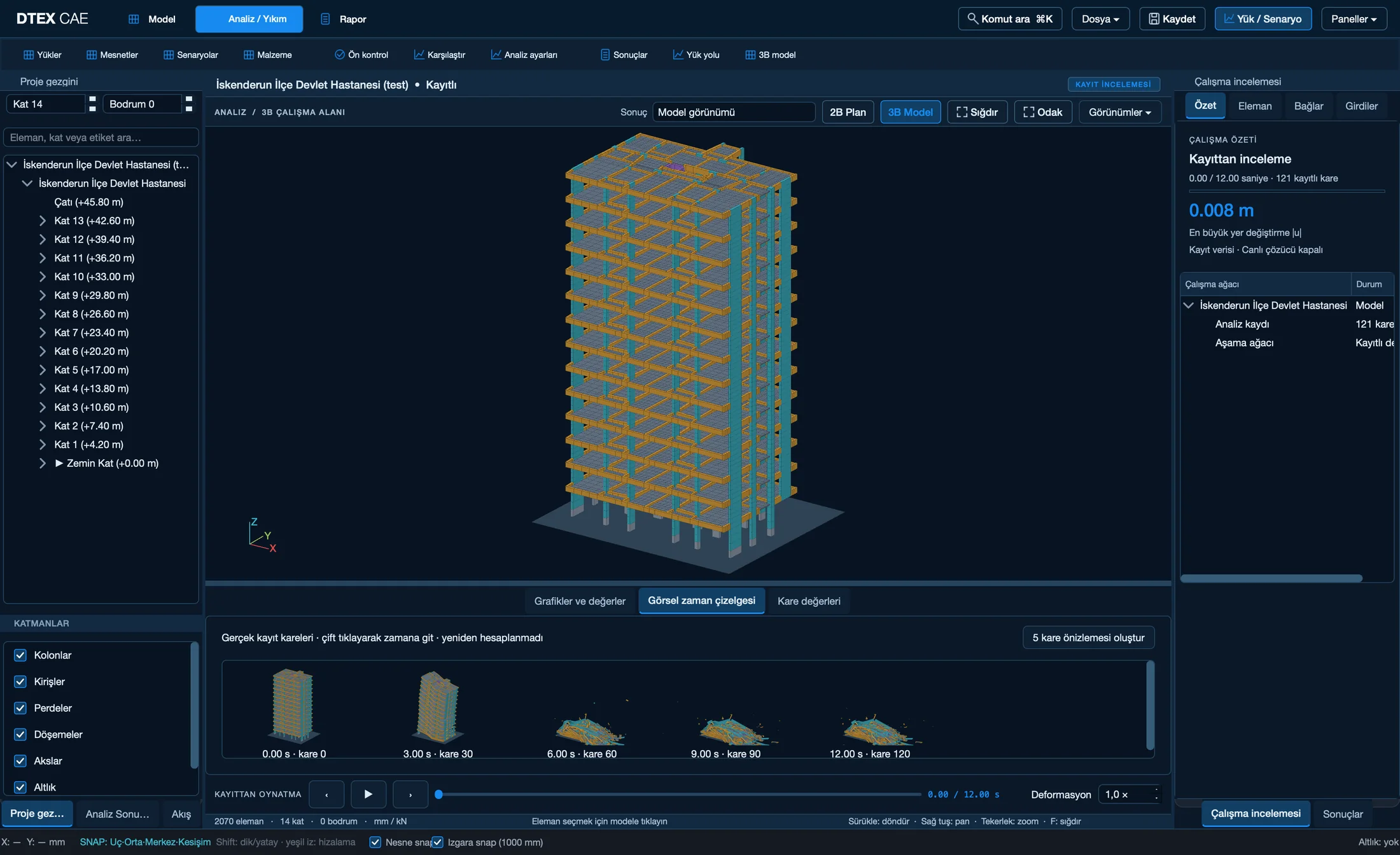
Project tree on the left, 2D/3D view in the centre, run summary on the right, timeline at the bottom.
- 01
Turkish-language command line
Command line and command centre.
- 02
Three workspaces
Modelling, analysis / demolition, reporting.
- 03
Autosave
Every four minutes; recovery after a crash.
- 04
Independent solver core
Solver core independent of the interface; one consistent unit system internally.
02Modelling
From project drawings to a 3D model
Architectural and structural drawings are opened as DXF, DWG or PDF and scaled to true size with two points. Column, beam, wall and slab candidates are recognised automatically; the model does not change until the engineer approves.

- MEM
Members
Columns, beams, shear walls, slabs; adding storeys and basements, copying storeys.
- RFT
Reinforcement
Beam top/bottom, column longitudinal, stirrup and wall reinforcement; flagged as an assumption in the report when no reinforcement drawing exists.
- MAT
Materials
Reinforced concrete material library: concrete and reinforcing steel grades; properties are calculated from the grade.
- SUP
Supports
Sliding or uplifting supports, loss of ground support.
- DWG
Drawings
Sections, elevations, sheets; DXF and PDF drawing output; reinforcement quantities.
- SIL
Silos
Unrolled silo shell, openings and reinforcement detailing.
03Structural analysis
Demand and capacity for every member
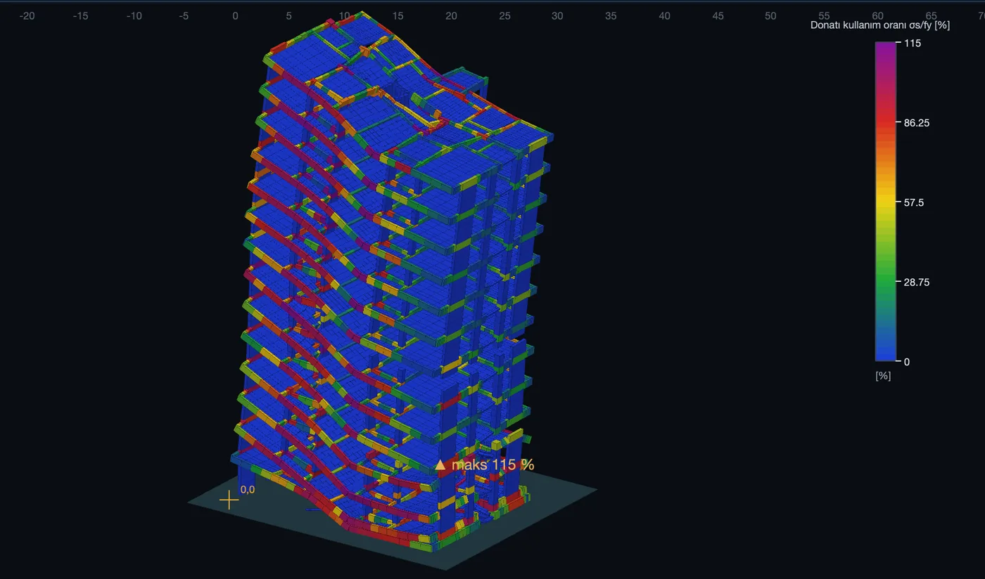
The model is solved as a 3D frame. When a load-bearing member is removed, the redistribution of load is calculated with the alternate load path method, giving a demand/capacity ratio (DCR) for every member. The demand/capacity ratio is the force acting on a member divided by the force it can carry; a member above 1 is overstressed.
- 01
3D space frame
P-Δ effects, buckling and modal analysis; storey drift.
- 02
Column capacity
Column N–M interaction diagram and section capacity.
- 03
Beams and walls
Beam and wall internal forces, punching shear check.
- 04
Criticality scan
The members that govern the stability of the structure.
- 05
Before and after
Automatic before/after removal comparison; load redistribution shares.
- Static verdict
- Stable · Local risk · Collapse
- Dynamic verdict
- Stable · Ongoing · Partial collapse · Total collapse
- Method
- Alternate load path
- Output
- DCR for every member
Result views
İskenderun hospital building model · removal scenario.
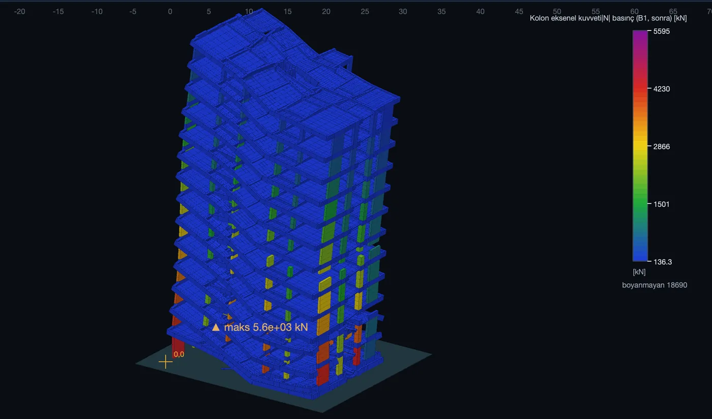
Column internal forces
Axial force and N–M utilisation.
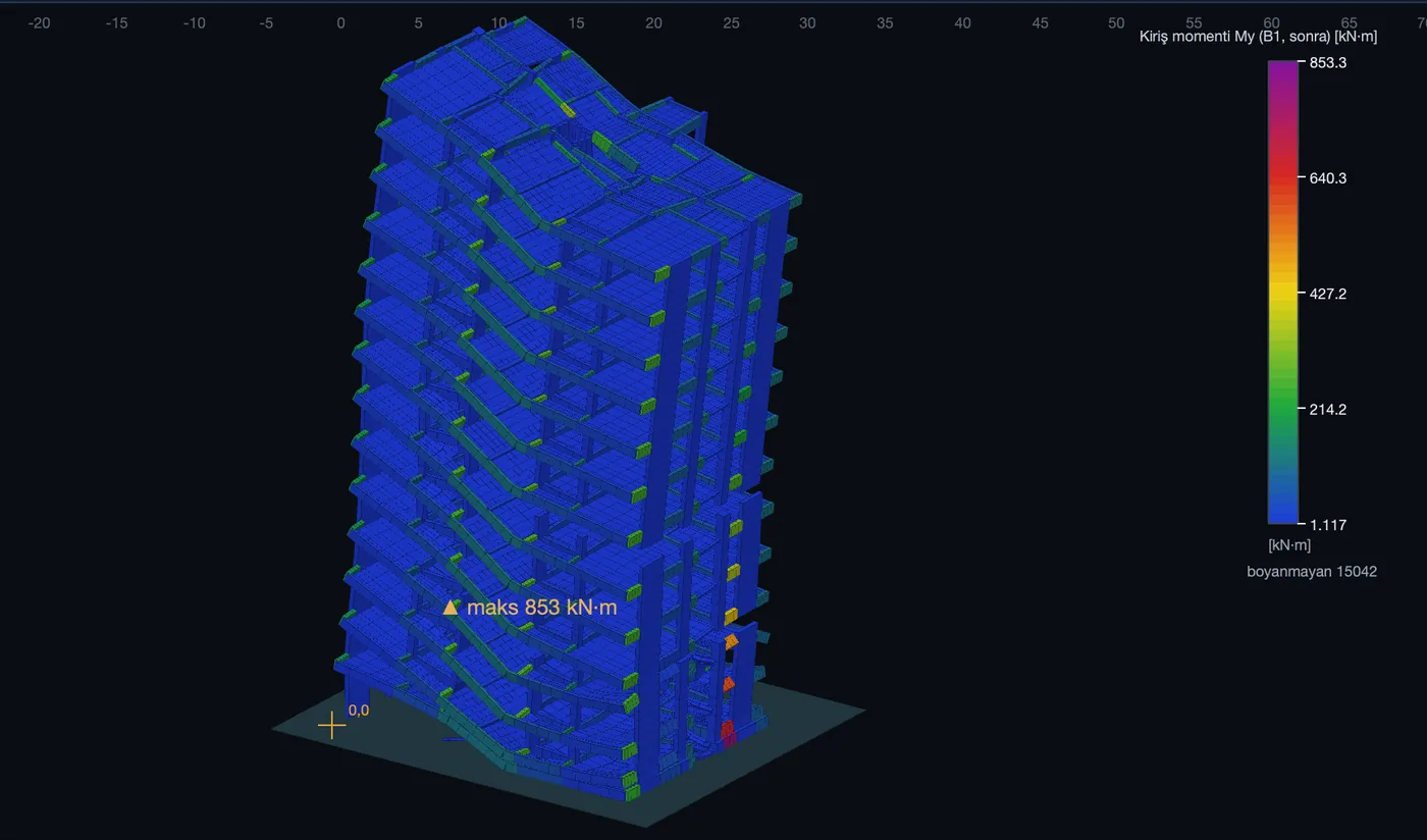
Beam internal forces
Moment, shear and demand/capacity ratio.
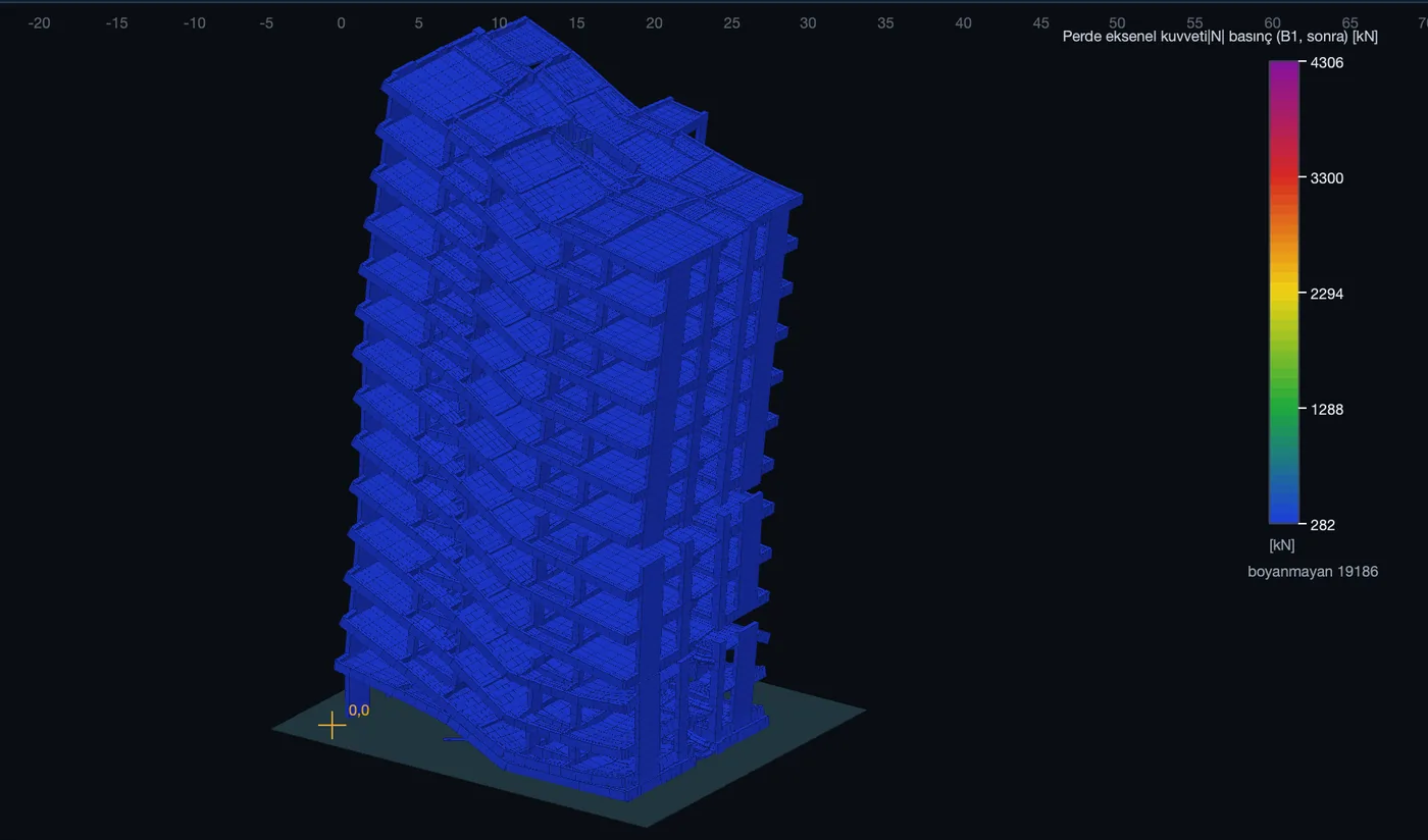
Shear wall results
Wall internal forces and load share.
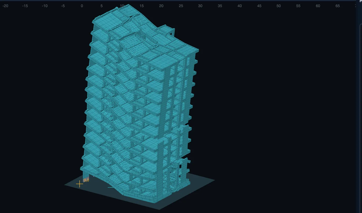
Criticality map
The governing members in a removal scenario.
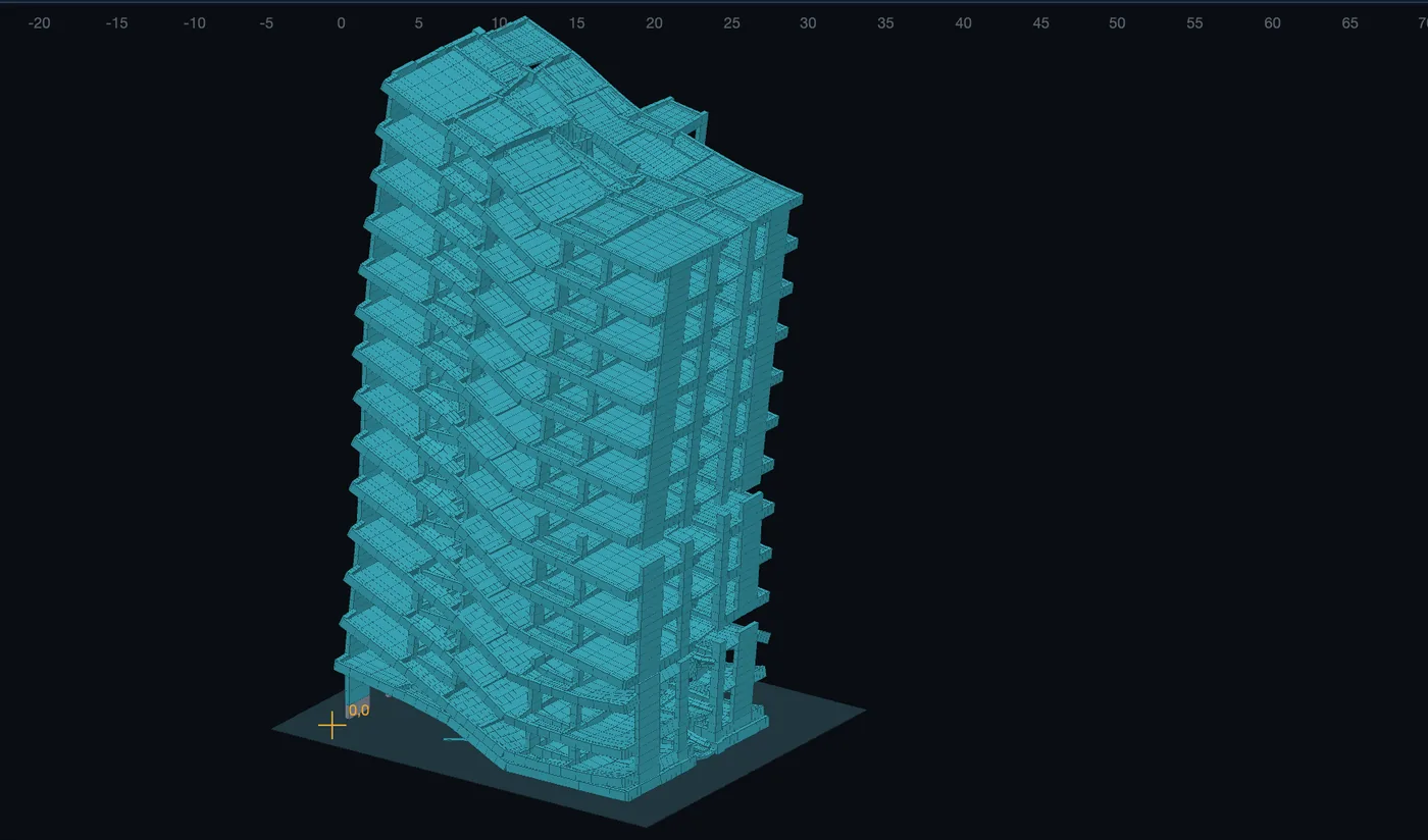
Load redistribution
Transfer of the removed member’s load to its neighbours.
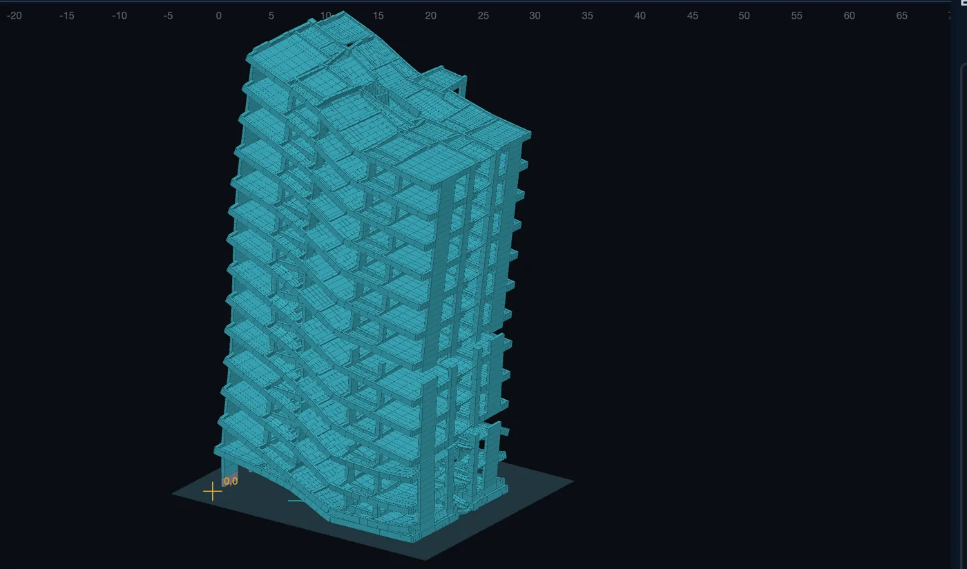
Zone of influence
Members affected by the removal and their level of criticality.
04Demolition scenario
Which member, in what order, and when?
The scenario is built from the members to be cut and the delays. At every stage you see what load-bearing system the structure has left; a removal sequence can be suggested from the demand/capacity ratios.
- REM
Removal
Sudden, staged, static or dynamic removal.
- STR
Strip
Strip removal by base gap and strip length; slab zones and wall strips.
- IMP
Implosion
Time-delayed implosion plan; staged removal in 3D.
- FEL
Felling
Directional felling of silos and chimneys; felling sequence for silo batteries.
- LDP
Load path
Which columns take the load of the removed column.
- SHR
Shoring
Temporary shoring and equipment loads enter the scenario.
Visual timeline
Playback · collapse frame by frame · two moments side by side.
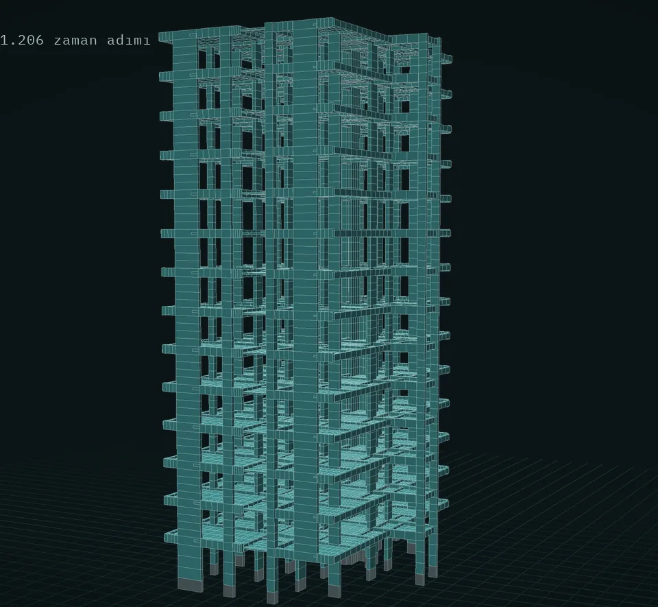
05AEM collapse analysis
The structure separates, collides and settles
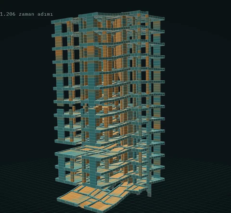
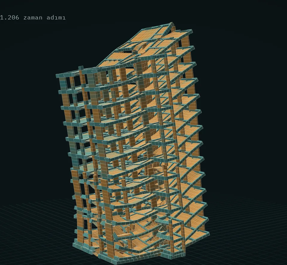
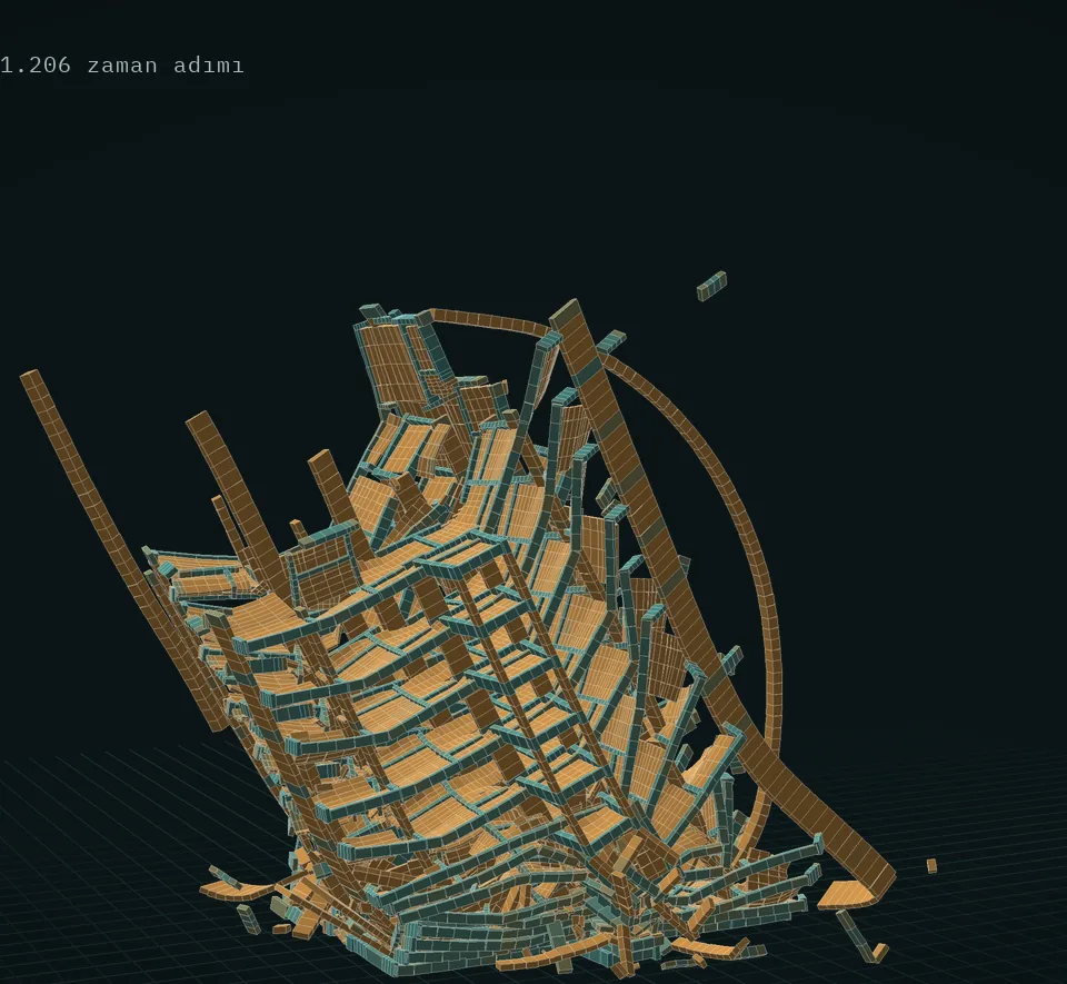
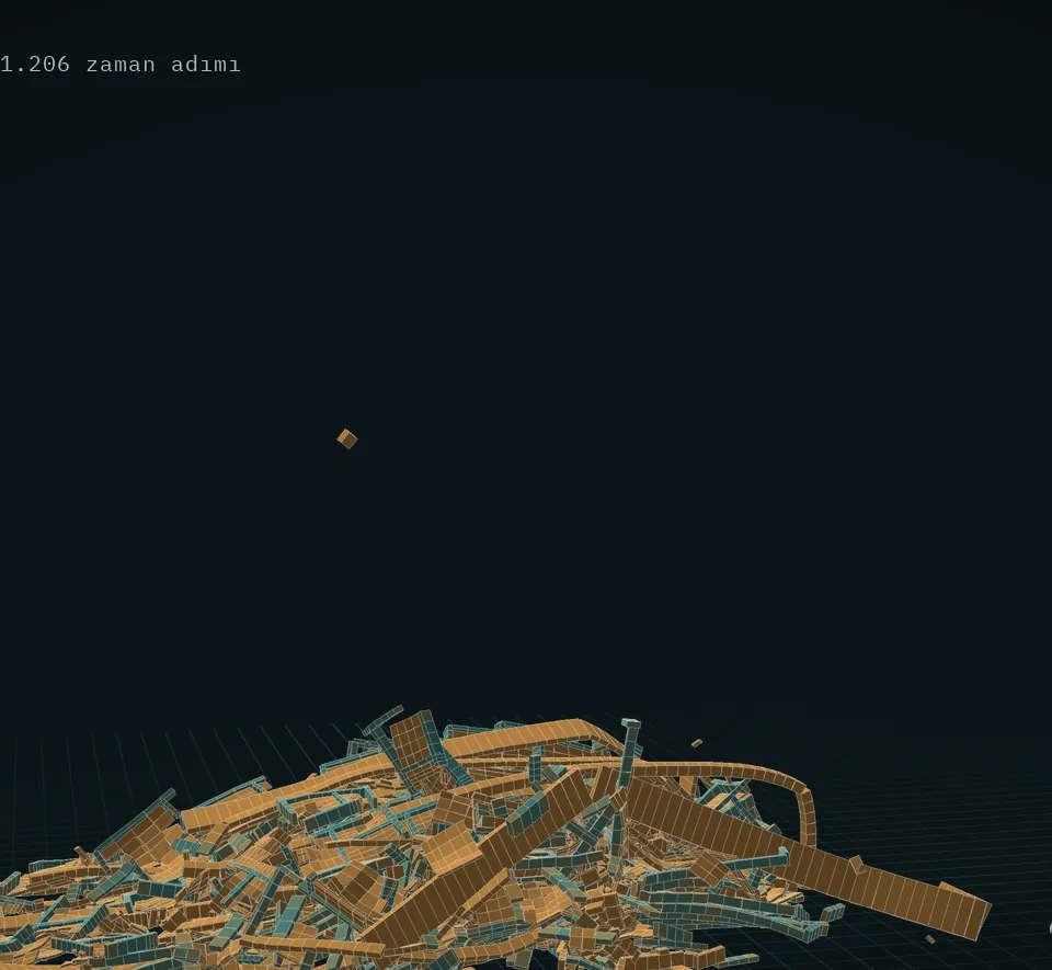
The Applied Element Method (AEM) models the structure as blocks connected by springs. As springs fail, members separate; blocks collide with each other and with the ground. Cracking, rebar rupture, storeys pancaking onto each other and the formation of debris are followed time step by time step.
- BLK
Block–spring
Separate constitutive laws for concrete and steel; bond–slip and rebar rupture.
- CNT
Contact
Block–block and block–ground collision.
- SLB
Slabs
Slab blocks: storeys pancaking and rubble behaviour.
- HNG
Hinges
Plastic hinge stages are stored in the record.
- DEB
Debris
Debris panel: spread, direction, pile height.
- REC
Record
Time series and energy log; frame sequence and video output.
Collapse analysis views
İskenderun hospital building model.
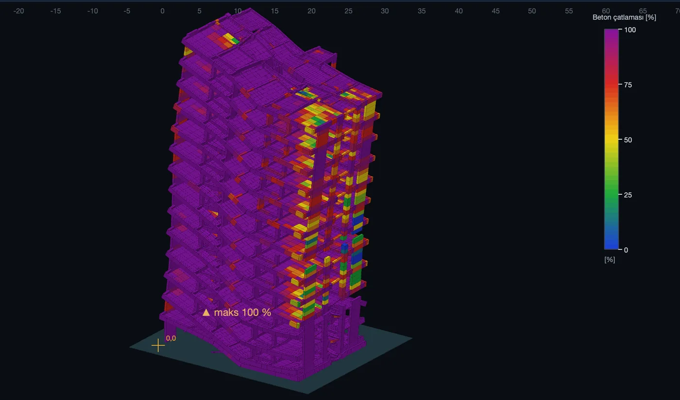
Concrete damage / cracking
How damage spreads through the members.
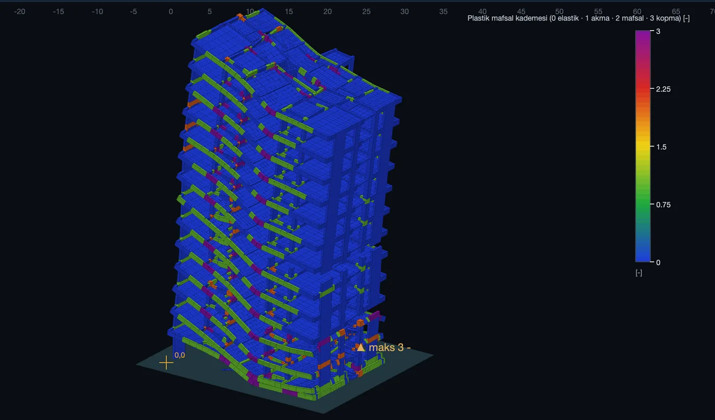
Plastic hinges
Points where the section reaches yield.
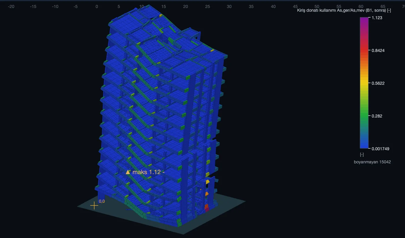
Reinforcement stress
Bars approaching yield and rupture.
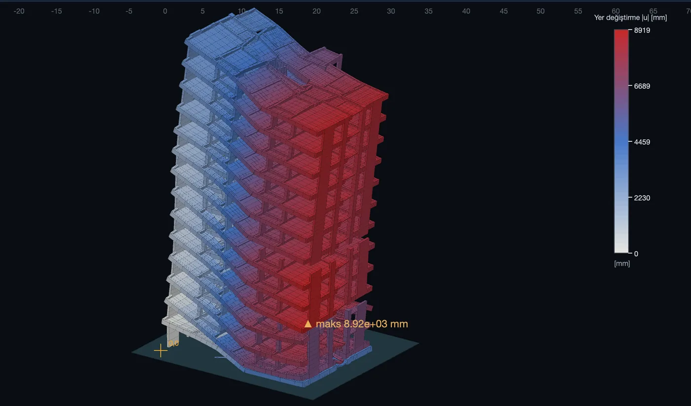
Displacement
The movement of every member during the collapse.
06In the field · İskenderun
Same camera, same second
The blast of the hospital building in İskenderun was recorded by drone. When the DTEX CAE model of the same building is played from the field camera’s angle and in real time, the collapse direction matches the field footage.
- Quantity compared
- Collapse direction
- Quantity compared
- Movement of the roof edge
- Playback
- Real-time match
Model output; field back-analysis. The comparison is visual and does not replace experimental validation at building scale. The software does not replace review by a competent engineer or field measurement; it supports them.
07Validation
Compared with tests, every result traceable
The AEM solver was compared with laboratory tests on reinforced concrete beam–column frames in which the middle column was removed (NIST TN 1720). Model parameters were not fitted to the test curves. In both frame types, five out of five criteria fell within the acceptance band.
| Intermediate moment frame | Special moment frame | |||||
|---|---|---|---|---|---|---|
| Criterion | DTEX CAE | Test | Diff. | DTEX CAE | Test | Diff. |
| Catenary peak loadkN | 569.0 | 547 | +4.0% | 1108.4 | 1232 | −10.0% |
| Catenary displacementmm | 1117.9 | 1092 | +2.4% | 1103.3 | 1219 | −9.5% |
| First peak loadkN | 313.9 | 296 | +6.0% | 828.9 | 903 | −8.2% |
Scope. The scope is the beam–column subsystem; the special moment frame result is obtained within a specific mesh range. This is not experimental validation at building scale. Catenary: the stage in which, after the middle column is removed, the beams carry load in tension like a cable.
Quality and traceability
Same input, same result.
- 01
More than 3,000 automated tests
Every version passes the test suite.
- 02
Reproducible results
Bit-for-bit reproducible results with locked package versions.
- 03
Sealed records
Run records and field observations are sealed with SHA-256.
- 04
Expectations first
Expectations are written down before the calculation; results that miss are recorded too.
- 05
Assumptions log
Limitations that cannot be closed are written in a separate section of the report.
- 06
Version trace
The version number is written into every report and run record.
08Reporting and decision support
The calculation, open to the engineer who decides
Every run is documented as a method statement, a technical report and a client report. Assumptions and limitations are stated plainly in the report; the program never says “removable” — the engineer decides.
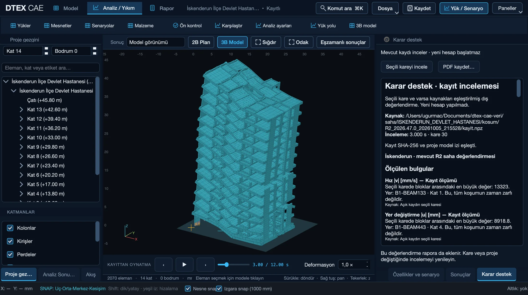
- 01
Reports
Method statement; technical and client report (DOCX).
- 02
Quantities and presentation
Reinforcement quantities (XLSX) and summary presentation (PPTX).
- 03
14 result views
Two moments of the same record compared side by side.
- 04
Timeline
Frame sequence and video output.
- 05
Decision support
Measured findings, possible explanations and uncertainties kept separate.
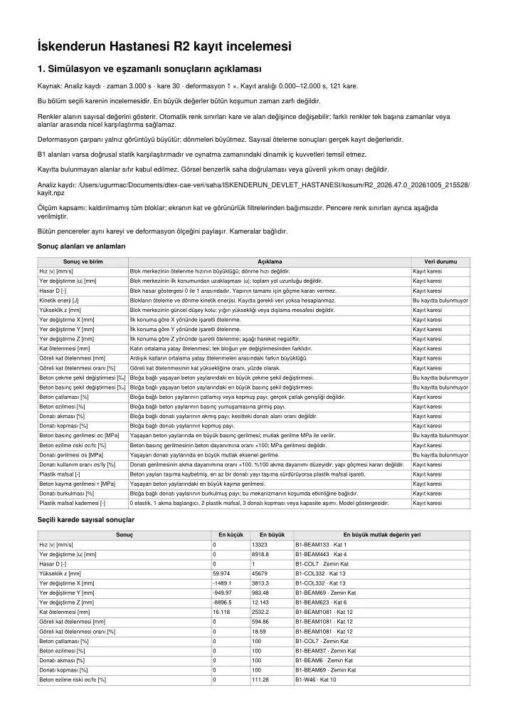
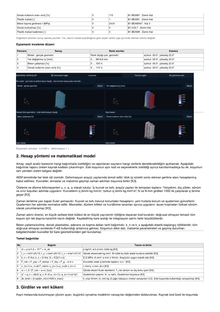
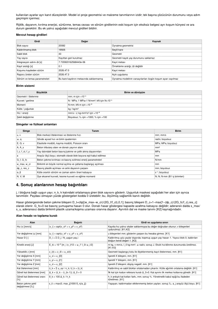
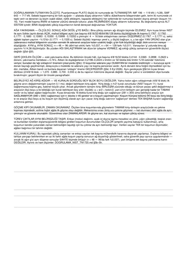
Sample report
İskenderun R2 record review · pages.
09Who it is for
One calculation for every side of a demolition
Building owners and contractors
Method, sequence and collapse direction for silo, chimney and building demolition, reported before the blast.
Public authorities
Calculation-backed demolition methods for technical specifications and tender preparation.
Engineering firms
Analysis services from DTEX for alternate load path and critical member assessment.
DTEX CAE analyses are carried out as part of DTEX engineering services; the results feed directly into the demolition design and the work on site.
How we work
From drawing to site.
- 01
Project and drawings
Location, drawings and schedule are shared.
- 02
Model and structural analysis
The 3D model is built and members are checked.
- 03
Demolition scenario
Cuts, stages and delay sequence.
- 04
AEM collapse analysis
Collapse direction, sequence and debris area.
- 05
Report
Technical and client report.
- 06
Execution and recording on site
Blast, measurement and comparison with the field record.
From analysis to blast, on our own record
—FAQ
Frequently asked questions
Which software do you use?
DTEX CAE, our own software. All rights are owned by DTEX; structural analysis uses a 3D frame and collapse analysis the Applied Element Method (AEM).
Can DTEX CAE be purchased or licensed?
No. DTEX CAE analyses are carried out as part of DTEX engineering services and feed directly into the demolition design.
Does it calculate vibration too?
No; DTEX CAE has no vibration (PPV) module. Vibration and air overpressure are measured on site by seismograph at every blast: Seismic Analysis.
Can an old building without reinforcement drawings be analysed?
Yes. Where reinforcement data is missing, the adopted value is flagged as an assumption in the report and verified by field survey.
How reliable is the result?
The solver was compared with the NIST TN 1720 laboratory tests; five out of five criteria within the acceptance band in both frame types. This applies to the beam–column subsystem and is not experimental validation at building scale. Assumptions and limitations are written separately in the report.
Do you provide a stability report?
Yes; the current condition of the structure and the blasting risks before demolition are reported in a stability report and risk analysis.
Work with us
Let’s start your project with a calculation
Share the location, drawings and schedule of the structure; let’s define the demolition method together with DTEX CAE.
- 013D model and structural analysis from project drawings
- 02Demolition scenario and AEM collapse analysis
- 03Technical and client report
- 04Technical specification and tender consultancy
—Related services