Drilling & Blasting Engineering

Drilling & blasting engineered for the rock: one team from design to firing

Blast pattern design, drilling, charging and delay firing for open pits, tunnels and excavation sites; every shot is verified with vibration monitoring and fed back into the next design in a closed loop.

Open Pit + TunnelDrilling & blasting capability in both settings
Electronic / NonelDelay initiation systems
kg/m³Powder factor designed to the target
PPV MonitoringMeasurement and reporting on every shot

Service Scope

From permits to firing: twelve service lines

The full chain — permits, technical specifications and procurement through site execution, measurement and reporting. Every project is designed to its rock mass, surroundings and fragmentation target; services are available individually or turnkey.

Open Pit Bench Blasting

01

Open Pit Bench Blasting

Pattern, charge and delay design to the production target; controlled bench shots.

Gallery / Tunnel Blasting

02

Gallery / Tunnel Blasting

Precise advance through face design, cut layout and perimeter hole control.

Excavation & Foundation Works

03

Excavation & Foundation Works

Low-vibration, small-diameter controlled shots near settlements and infrastructure.

Blast Design & Modelling

04

Blast Design & Modelling

Fragmentation, muckpile and vibration prediction; closed-loop optimisation with post-blast analysis.

Vibration Monitoring & Reporting

05

Vibration Monitoring & Reporting

PPV and air overpressure measurement, standard-based assessment and a signed report.

Drilling Service (Rock Drill / DTH)

06

Drilling Service (Rock Drill / DTH)

Holes true to pattern with measured deviation; quality control through drill logs.

Explosive Bolt Design

07

Explosive Bolt Design

Custom bolt and nut design that releases diversion tunnel gates within seconds in an emergency.

Engineering Tools & Software

08

Engineering Tools & Software

We build project-specific calculation tools and software for blast design, powder factor and cost estimation.

Specification & Procurement Consultancy

09

Specification & Procurement Consultancy

Technical specifications, contractor agreements and acceptance criteria for explosive procurement by public and private organisations.

Permits & Licensing

10

Permits & Licensing

Explosive purchase and use permits; regulation-compliant follow-through from application file to permit delivery.

Training & Field Support

11

Training & Field Support

Crew training on storage, charging and firing practice; on-site supervision during the first shots.

Underwater Drilling & Blasting

12

Underwater Drilling & Blasting

Specialised blasting for harbours, cofferdams and underwater excavation using waterproof charges and delay firing.

Method & Design

Milliseconds govern the rock

Move your cursor over the panel — in this 4-row × 7-hole bench model, initiation starts at the free face and steps back row by row. As the front row throws rock forward, the rows behind break to the new void: vibration drops, fragmentation and muckpile shape stay under control.

Delay Firing — 3D Bench Model Move your cursor over the panel
  1. 01
    Site survey and designRock unit, discontinuities and surroundings inventory; pattern, charge and delay plan.
  2. 02
    Drilling and controlDrilling to pattern; hole depth, deviation and water condition are logged.
  3. 03
    Charging and stemmingCharge placement to design, stemming and a hook-up checklist.
  4. 04
    Delay firingSequenced initiation with electronic or nonel systems; minimum charge per delay.
  5. 05
    Measurement and reportingPPV records, muckpile and fragmentation analysis; results feed the next design.

Specialised Blasting Application

Underwater drilling & blasting

Harbour and berth deepening, excavation inside cofferdams and removal of submerged rock levels are done by delay-firing holes drilled underwater and loaded with waterproof charges. The water column acts as stemming — the design goal is to break the rock at the planned level while keeping water shock and scatter within limits.

  1. 01
    Bathymetry and bed profileWater depth, rock-bed profile and excavation level are surveyed; hole depth and pattern follow.
  2. 02
    Underwater drillingCasing-guided drilling from a pontoon or platform; level and deviation logged for every hole.
  3. 03
    Waterproof chargingCharges and detonators rated for water pressure and sleep time; circuit continuity tested underwater.
  4. 04
    Delay firingThe water column acts as stemming; the delay plan limits water shock and heave.
  5. 05
    Monitoring and surveyIn-water pressure and vibration measurement; post-blast depth survey verifies the excavation level.
Moment of the shot — first break at the water surface
Heave developing in delay sequence
Rise of the water column
Fully developed water column
Close-up — column and scatter control
Submerged excavation level and drill line
Cofferdam wall and water inlet
In-water excavation and charging platform

Custom Engineering

Explosive bolt: a design that releases the diversion gate within seconds

When a diversion tunnel must discharge in an emergency, the gate has to open without delay. Mechanical release mechanisms can seize under load at that moment; an explosive bolt instead uses a small charge placed inside the nut to cut it at a designed section and free the bolt instantly.

DTEX designs these bolts: the shear section for the gate load, the charge cavity inside the nut, the charge weight and the firing circuit are calculated per project — and verified with a full-scale trial shot before going to site.

  1. 01
    Gate and load analysisGate geometry, water load and the tensile force per bolt are determined.
  2. 02
    Bolt–nut geometryThe cavity machined into the nut, the shear section and the notch geometry define the plane where separation will occur.
  3. 03
    Charge and detonator placementThe smallest charge that defeats the shear section is selected; detonator and firing line are routed out through the nut.
  4. 04
    Verification by trial shotA full-scale assembly is fired on steel plate of the same thickness; separation at the designed section is inspected and confirmed.
  5. 05
    Installation and commissioningTorque-controlled installation on site, circuit continuity testing and safe handover of the firing circuit.
Explosive bolt assembly — firing line connected
Components and dimensional check
Charge cavity inside the nut
Charge and detonator preparation
Mounting on the trial plate
After the shot — nut cut, bolt released
Nut fragments separated at the designed section
Inspection of the shear section
Blast mat — fragment scatter control

Preliminary Assessment

Try the powder factor yourself

Adjust the pattern and charge to pre-assess the explosive consumed per cubic metre of rock (powder factor).

q = Q / (B · S · H)

0.52kg/m³

Rock volume per hole: 105

0lighttypical open pithard rock1.5

This calculation is for preliminary assessment. The final pattern is designed on site to the rock unit, discontinuities, hole diameter and fragmentation target.

Engineering Tools

International Framework

Design and monitoring follow recognised international standards

Blast-induced vibration is assessed and reported against whichever of the standards below fits the project geography, structure type and employer specification.

USBM RI 8507

Structure response limit curves

Frequency-dependent PPV limit curves; the common reference for residential structures.

OSMRE 30 CFR 816.67

Blasting control criteria

Distance-based maximum allowable PPV and scaled distance application rules.

DIN 4150-3

Vibration effects on structures

Short-term vibration thresholds by structure type and frequency band.

BS 7385-2

Building damage assessment

Setting cosmetic damage thresholds for transient vibration.

ISO 4866

Measurement and evaluation principles

Sensor placement, recording and data processing principles.

EN 13630 / EN 13763

Explosive product standards

Conformity requirements for safety fuse, detonators and initiation systems.

Field Media

Frames from the operation

Videos play on hover; every frame enlarges on click. All footage is from the DTEX archive.

Mines & Quarries — Surface Blasting
Pipeline, Trench & Gallery Drilling and Blasting
Bench blast — aerial view
Sequenced shot — delay columns
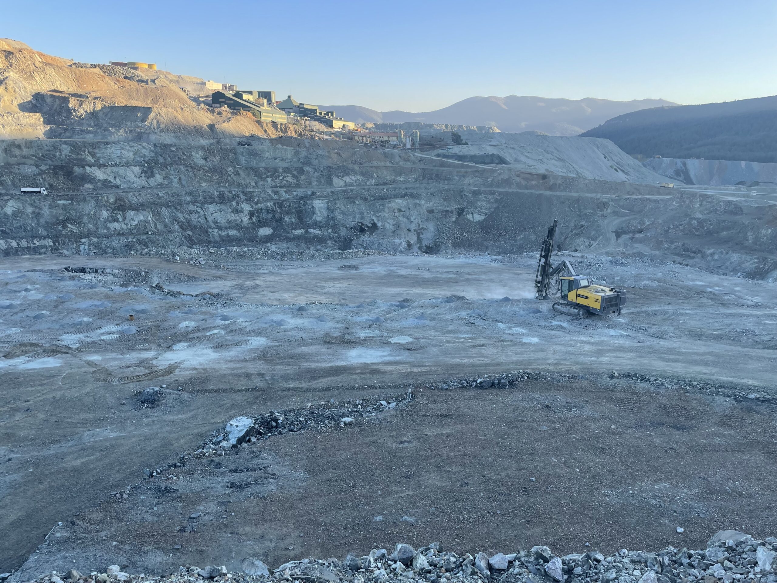
Drill pattern — production bench
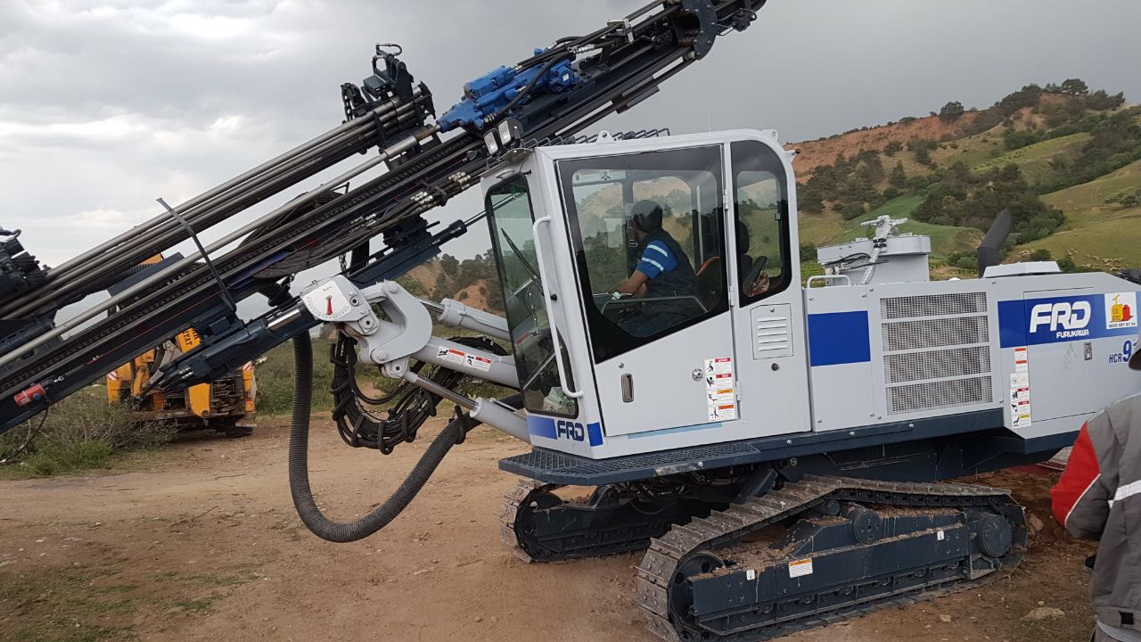
Drill rig supply matched to the geology
Drill Rig Supply Matched to the Geology
Tunnel drilling machine supply and blasting
Tunnel Drilling Machine Supply and Blasting
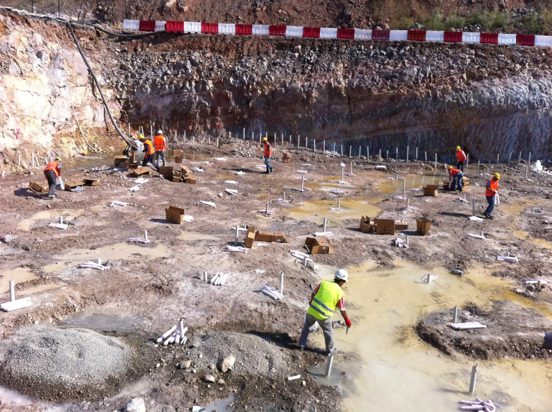
Charging crew — foundation excavation
Construction foundation drilling and blasting
Construction Foundation Drilling and Blasting
Foundation excavation — drilling and dewatering
Which permits are required for blasting?

An explosive purchase and use permit, certified blaster qualifications and a site-specific safety plan are required. After the project survey we provide you with the permit list and its timeline.

Can blasting be done near settlements?

Yes — a structure inventory is compiled, site constants are established with a trial shot, and the charge and delay design is set to the limit of the selected standard. Every shot is recorded with a vibration monitor.

Why does delay firing matter?

When holes fire in sequence at millisecond intervals, the charge detonating at any instant is smaller; vibration drops, rock is thrown forward in a controlled way and fragmentation improves.

How is flyrock prevented?

Through correct bottom charge, adequate stemming, pattern discipline and shot direction control; blast mats are used where needed and safety distances are defined in the site plan.

Can fragment size be guaranteed?

Fragmentation is a function of rock mass, pattern and powder factor. The target size is set to crusher/screen capacity, measured with post-blast image analysis, and the design improves with every shot.

Do you obtain the explosive permits?

Yes. We run the explosive purchase and use permit process in line with national legislation and the international rules the project is subject to — from preparing the application file to delivery of the permit.

What do you prepare for specifications and contracts?

For explosive procurement by public and private organisations we prepare regulation-compliant technical specifications and contract annexes covering needs definition, product and equipment characteristics, acceptance criteria, safety and storage conditions and contractor obligations.

What does training and field support cover?

It spans the process from explosive supply to the final application on site: crew training on storage and transport rules, charging and firing practice, safety instructions and record keeping; on-site supervision during the first shots and ongoing consultancy afterwards.

How is the charge protected in underwater blasting?

Because the hole is full of water, waterproof charges and detonators rated for water pressure and sleep time are used. Circuit continuity is tested underwater, and the time from charging to firing is limited in the design.

What about effects on marine life?

The impact is assessed through the in-water pressure wave (overpressure). The delay plan reduces the charge firing at any instant, damping measures such as bubble curtains are applied where needed, and measurement records are reported.

What is an explosive bolt and why use one?

Diversion tunnel gates must be released within seconds in an emergency. Mechanical release mechanisms may not operate reliably in that window; in an explosive bolt, a small charge placed inside the nut cuts it at a designed section and frees the bolt instantly.

How is an explosive bolt verified?

Before installation, a full-scale assembly is mounted on steel plate of the same thickness and trial-fired. Separation at the designed section, absence of plate damage and fragment scatter contained by the blast mat are inspected and confirmed.

Can I get only drilling or only monitoring?

Yes. Drilling, blast design and vibration monitoring services are also available separately.